Innovative plant technology
Although synthetic lawn had been introduced in American baseball stadiums already at the end of the 1960s, it only became an accepted alternative to the high-maintenance natural lawn at the turn of the millennium. But after 12 to 15 years of use, up to 5000 artificial turf sports fields are currently due for renovation in Germany alone. This raises the question of the best possible disposal. Up-to-date the only serious answer is: “Recycling”. The Austrian extrusion and recycling technology company MAS offers innovative system technology for converting old and worn artificial grass efficiently and cost-effectively into high-quality plastic granulate.
Artificial grass is the resilient alternative to natural lawn
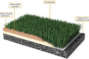
If lawn sports fields are to be used all year round and to have uniform characteristics of use and visually appealing qualities regardless of environmental influences, there is no way around synthetic lawn. Especially if, in addition to a high level of use, increasing climatic extremes, such as long periods of dryness or heavy rain events, affect a natural lawn. The artificial grass its premiere in 1966 on the playing ground of the Astro-Dome in Houston. It was a carpet-like flooring, made from polyamide yarns. But as it was laid without a shock-absorbing substructure or filling material it posed a risk of injury for the players. In the 1980s an evolutionary version was introduced with the grass blades made from polypropylene strips and sand as the filler material. This reduces the injury risk, but there was still a lack of impact damping properties. The next evolutionary stage in the 1990s combined PP and HDPE grass mats with sand and rubber granulate fillings, which offered the desired damping properties and made the UEFA and FIFA approving synthetic lawn systems for football stadiums. At the beginning of the 2000s, the 4th generation of artificial lawn systems came onto the market. Their distinguishing feature is the combination of stiff, upright and soft, curled PE-grass blades on a PP base fabric. The stalks and carrier fabric are joined together on a so-called tufting machine. There, the stalks are fed from rolls as yarn, pierced into the carrier fabric and then usually cut to a length of 42 mm. The blades are permanently fixed by coating the back of the fabric with a latex/PU-adhesive. After laying, the artificial grass is filled up to a height of 30 mm with sand and shock-absorbing rubber granulate. This combination comes very close to a natural turf without showing its sensitivity to mechanical and climatic stresses (Fig. 1).
Innovative recycling methods turn artificial grass sustainable
Experience has shown that an artificial grass system can be in intense use for 12 to 15 years before it is due for renewal. And there is the question regarding the best possible disposal. As landfilling or thermal disposal in waste incineration are no longer accepted options due to the sharp increase in quantities there is no getting around recycling. Especially since better and more cost-effective methods are available to recycle almost 100 % of the plastic and single-material systems are in the pipeline. The later in order to improve recyclability through the manufacture of the blades of the synthetic grass and the base fabric from the same material (PE) and to replace the method of connection by gluing by means of thermo-fixation. This will significantly simplify the technical efforts required for recycling. But as the single-material systems are just to be introduced they will be due for renewal only in 12 to 15 years. But until then, also conventional synthetic lawn can be recycled into valuable secondary raw materials.
The MAS-Recycling-Options
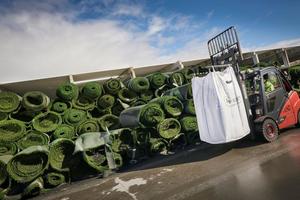
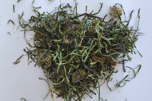
The renewal begins with the removal of the worn lawns (Fig. 2). But before these can be removed and rolled up, the filling material (rubber granulate and sand) is to be vacuumed off. The better and more thoroughly these extraneous materials can be separated, the easier is the further processing of the old lawn. The next recycling step is the shredding down to particles 10 to 40 mm in length with a bulk density (uncompacted) of approx. 50 to 100 g/l (Fig. 3).
The shredded material consists of:
approx. 40 % PE (the actual grass-blades)
approx. 20 % PP (base fabric)
approx. 40 % latex/natural rubber or PU (backing on the base fabric)
It contains up to 15 % by volume of impurities, consisting of:
up to 8 % extraneous materials (dust, sand, soil)
up to 1 % rubber (old tire granulate) or EPDM from approx. 2 mm down to dust,
3 - 5 % moisture
Material tests have shown that the MAS-system-technology is capable to process this PE/PP-fiber-mixture into a high-quality plastic granulate. Their basic processing component is the DRD (Double Rotary Disc) dry cleaner-unit.
Processing stage 1: dry cleaning – simple but effective
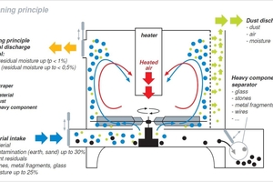
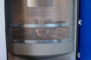
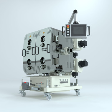
The shredded material is fed to the DRD (Double Rotary Disc) dry cleaner. In it the majority of all granular contaminants and moisture adhering to the fiber material is efficiently separated. It is basically a centrifuge with a double rotor system running inside. Double because the rotor disc has differently shaped rotor blades on the bottom and top (= patented double rotor disc system). The system is operated in batches. The underside of the rotor sucks the shredded material out of a buffer container and transports it into the centrifuge. Gravity ensures that larger and heavy contaminants, such as metal parts, stones, etc. are not transported into the process chamber at all, but are separated into an upstream heavy material separator (Fig. 4). Subsequent, the pre-cleaned material is forced into a turbulent hot air circuit by the rotor. The warm air absorbs the moisture and transfers it off in exchange with the outside air. The warm air is generated via a central heating element register. In addition, the declining moisture content and the friction between the plastic particles created by the turbulence cause residual dirt to be separated off tangentially by centrifugal force via lateral separation sieves (Fig. 5). The cleaned plastic batch is then discharged at periodic intervals by centrifugal force after opening a pneumatic flap and fed to a material silo.
Processing stage 2: plasticizing, filtering and degassing
The plastic fraction fed from the DRD-dry-cleaner via the buffer silo to the extruder consists of the above-mentioned components PE (grass blades), PP (base fabric) and latex/PU (adhesive layer), as well as marginal residual amounts of rubber granulate.
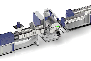
For the further processing of this input material MAS has developed an extrusion cascade consisting of a conical twin-screw extruder with degassing unit, a subsequent continuous melt filter, a single-screw extruder and a granulating station (Fig. 6). The advantage of the conical MAS-extruder is the system-specific large cross-section of the feed opening. This makes it particularly suitable for materials with a low bulk density, such as synthetic lawn fiber flakes.
The co-rotating MAS-twin-screw-principle is characterized by a plasticization at a comparatively lower mean pressure and level of shear and a highly uniform melt flow with excellent homogenization. The latter is particularly important for recycling applications. This is because it is the prerequisite for the release of undesired plastic fractions in gas form and filtering.
The plastic melt is conveyed from the MAS extruder through a CDF (Continuous Disc Filter)-melt-filter-unit, developed and patented by MAS for recycling applications. The core component of all CDF-filters is a filtration disk rotating in the incoming melt flow. It holds back the impurities, in the specific case remaining rubber particles or unmolten plastic particles. The filter discs are made of hardened steel and, depending on the application, are available with filtration fineness from 90 µm to 1000 µm. The impurities are wiped off from the rotating filter-disc by a stationary scraper in the filter housing. From there a screw conveyor conveys them together with a minimum amount of plastic to the outside. The melt-filter-series is matched to the MAS-extruders and for throughputs of up to 2 t/h.
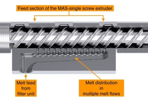
From the CDF filter, the melt flows via a special distributor block into the subsequent single-screw extruder, equipped with a second degassing-station. This offers a procedural innovation. It is the patented division of the melt flow into a series of individual flows (Fig. 7). This division ensures that the pre-cleaned polymer-mixture can consequently be degassed in the single-screw-extruder more efficiently due to the increased melt surface. From the single-screw extruder, the melt is either fed to a pelletizer or processed further in-line.
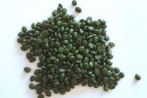
The outcome is a high-quality-PE/PP-granulate for a variety of different quality products, e.g. films, as could be documented by a series of plasticizing tests (Fig. 8). This opens up the potential for one or more „reincarnations“ of worn artificial grass in other applications or products.

